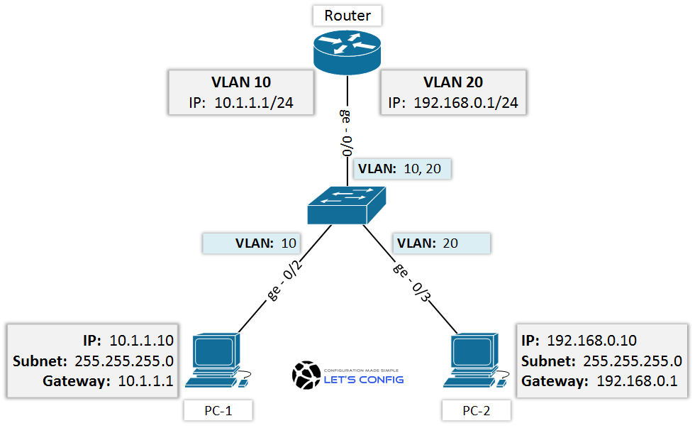
When we have VLANs in our network, two separate VLANs can’t communicate between them, unless we do the routing between them. Which means, we need a router (L3 device) to make communication between them. In this lesson, we will configure router for inter VLAN routing.
To do that, we will follow below topology and our goal will be to establish ping between PC-1 to PC-2.

Fist of all, let’s check current configuration on the switch.
VLANs:
Switch#show vlan

VLAN Name                             Status    Ports
---- -------------------------------- --------- -------------------------------
1    default                            active        Gi0/1, Gi1/0, Gi1/1, Gi1/2
                                                            Gi1/3, Gi2/0, Gi2/1, Gi2/2
                                                            Gi2/3, Gi3/0, Gi3/1, Gi3/2
                                                            Gi3/3
10   vlan-10                          active      Gi0/2
20   vlan-20                          active      Gi0/3
1002 fddi-default                    act/unsup
1003 token-ring-default          act/unsup
1004 fddinet-default               act/unsup
1005 trnet-default act/unsupInterfaces:
interface GigabitEthernet0/2
 switchport mode access
 switchport access vlan 10
!
interface GigabitEthernet0/3
 switchport mode access
 switchport access vlan 20
!
interface GigabitEthernet0/0
 switchport trunk allowed vlan 10,20
 switchport trunk encapsulation dot1q
 switchport mode trunk
(If you want to learn more about, click how to configure VLAN on Cisco catalyst switch)
Inter VLAN routing configuration:
To configure inter-vlan routing, we need to configure the interface as sub-interfaces. According our diagram, we need to configure ge-0/0 for this.
Let’s begin with, no shutdown command for the physical interfaces. Keep in mind, without making physical interface UP, whatever you do in sub-interfaces, it will not work.
Router(config)interface GigabitEthernet0/0
 no shutdown
Now, we will configure sub-interface for VLAN 10. We need to give our sub-interface a number and this number could be any between 0-4294967295.
Router(config)#interface gigabitEthernet 0/1.?
  <0-4294967295>  GigabitEthernet interface number
We will follow vlan number as our sub-interface number. So, our sub-interface will be ge-0/0.10 for vlan 10 and ge-0/0.20 for vlan 20 and we will give appropriate IP addresses.
interface GigabitEthernet0/0.10
 encapsulation dot1Q 10
 ip address 10.1.1.1 255.255.255.0
 no shutdown
interface GigabitEthernet0/0.20
 encapsulation dot1Q 20
 ip address 192.168.0.1 255.255.255.0
 no shutdown
Verify the interface using show IP interface brief command-
Router#show ip interface brief
Interface                         IP-Address      OK? Method Status                Protocol
GigabitEthernet0/0           unassigned       YES unset    up                    up
GigabitEthernet0/0.10      10.1.1.1           YES manual  up                    up
GigabitEthernet0/0.20      192.168.0.1     YES manual  up                    up
Finally, we will test it from User PC-1 (10.1.1.10) to PC-2 (192.168.0.10).
PC-1> ping 192.168.0.10
84 bytes from 192.168.0.10 icmp_seq=1 ttl=63 time=11.725 ms
84 bytes from 192.168.0.10 icmp_seq=2 ttl=63 time=12.619 ms
84 bytes from 192.168.0.10 icmp_seq=3 ttl=63 time=12.731 ms
84 bytes from 192.168.0.10 icmp_seq=4 ttl=63 time=14.143 ms
84 bytes from 192.168.0.10 icmp_seq=5 ttl=63 time=12.198 ms


Lean more about networking