Earlier, we have learned, how to configure OSPF on CISCO routers. Today, in this lesson, we will learn how to configure OSPF on Juniper. This process is same for MX, ACX, SRX, EX, and other Junos enabled devices.
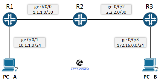
We will be using following topology for our LAB. So, let’s config 🙂

Configure OSPF on Juniper:
First of all, let’s configure IP addresses for all the devices.
R1:
set interfaces ge-0/0/0 unit 0 family inet address 1.1.1.1/30
set interfaces ge-0/0/1 unit 0 family inet address 10.1.1.1/24
R2:
set interfaces ge-0/0/0 unit 0 family inet address 1.1.1.2/30
set interfaces ge-0/0/2 unit 0 family inet address 2.2.2.1/30
R3:
set interfaces ge-0/0/2 unit 0 family inet address 2.2.2.2/30
set interfaces ge-0/0/3 unit 0 family inet address 172.16.0.1/30
PC:
PC-A: 10.1.1.10/24
PC-B: 172.16.0.10/24
Now, we will move to the OSPF configuration by enabling it. To enable OSPF in JunOS we need to define the interfaces on which it will run and the area to which the interfaces will be attached.
R1:
set protocols ospf area 0.0.0.0 interface ge-0/0/0.0
set protocols ospf area 0.0.0.0 interface ge-0/0/1.0
Here, we have configured OSPF area 0 (0.0.0.0) on interface ge-0/0/0.0 and ge-0/0/1.0 for router R1. Now, let’s do the same for other two Juniper routers.
R2:
set protocols ospf area 0.0.0.0 interface ge-0/0/0.0
set protocols ospf area 0.0.0.0 interface ge-0/0/2.0
R3:
set protocols ospf area 0.0.0.0 interface ge-0/0/2.0
set protocols ospf area 0.0.0.0 interface ge-0/0/3.0
Verifying OSPF on Juniper:
To verify OSPF on Juniper, we need to use “show ospf neighbor” command, which will show the current OSPF neighbor relationship with other routers.
root@R1> show ospf neighbor
Address          Interface              State     ID                 Pri    Dead
1.1.1.2          ge-0/0/0.0             Full      1.1.1.2          128    39
We can see from the above output for R1, where an OSPF neighbor relation is built using ge-0/0/0.0 interface which is in full state (active).
If we want to check which interfaces are now in OSPF database, then we need to use “show ospf interface” command. Below are the output from router R1.
root@R1> show ospf interface
Interface           State   Area            DR ID           BDR ID          Nbrs
ge-0/0/0.0          DR      0.0.0.0         1.1.1.1         1.1.1.2            1
ge-0/0/1.0          DR      0.0.0.0         1.1.1.1         0.0.0.0            0
Now, let’s check routing table.
root@R1> show route

inet.0: 7 destinations, 7 routes (7 active, 0 holddown, 0 hidden)
+ = Active Route, - = Last Active, * = Both

1.1.1.0/30         *[Direct/0] 01:35:01
                    > via ge-0/0/0.0
1.1.1.1/32         *[Local/0] 01:35:01
                      Local via ge-0/0/0.0
2.2.2.0/30         *[OSPF/10] 00:09:23, metric 2
                    > to 1.1.1.2 via ge-0/0/0.0
10.1.1.0/24        *[Direct/0] 01:35:01
                    > via ge-0/0/1.0
10.1.1.1/32        *[Local/0] 01:35:01
                      Local via ge-0/0/1.0
172.16.0.0/24      *[OSPF/10] 00:09:22, metric 3
                    > to 1.1.1.2 via ge-0/0/0.0
224.0.0.5/32       *[OSPF/10] 00:51:38, metric 1
                      MultiRecv
Routing table clearly shows, we are receiving routes from R3 via R2 using OSPF protocol along with our routes.
Finally, we will verify it by pinging from PC-A to PC-B.
PC-A:\>ping 172.16.0.10

Pinging 172.16.0.10 with 32 bytes of data:
Reply from 172.16.0.10: bytes=32 time=4ms TTL=64
Reply from 172.16.0.10: bytes=32 time=3ms TTL=64
Reply from 172.16.0.10: bytes=32 time=1ms TTL=64
Reply from 172.16.0.10: bytes=32 time=6ms TTL=64

Ping statistics for 172.16.0.10:
    Packets: Sent = 4, Received = 4, Lost = 0 (0% loss),
Approximate round trip times in milli-seconds:
    Minimum = 1ms, Maximum = 6ms, Average = 3ms

Hello, I’m trying to configure OSPF for SRX240 and RB750Gr3. When I configure in L3 interface, this works fine, I can see everything right in neigbohr. But I want to configure on a vlan interface. If I do this, the configuration doesn’t work. Have you seen this before?
It should work. Share us your configuration details. And, also share output of all verification commands.
Mr. Rajib thank you for all your efforts, its been very easy to understand and configure the way u did.
God bless you,
Thanks man.
very intersting thank you
You are welcome 🙂